Video for our Yoyo: YOYOMATO
Lyrics:
Student, who's in 008
(I said) You will get in teams and create
(plastic) Yoyos, and they're going to be great
You will manufacture fifty
Lecture where you learn theory
(and then) Lab time where you work the machines
It’s a great class, and I'm sure you will find
All the ways to yoyo design,
It's fun to be part of Yoyomato
It's fun to be part of Yoyomato
One side looks so delish, other side is a fish
Designing all day long
It's fun to be part of Yoyomato
It's fun to be part of Yoyomato
It looks incredible, practically edible
Redesigning all day long
Rice ring that the basepiece will hold
(we will) CAD out every grain cause we're bold
(then we) 3D print that thermoform mold
It will rice to the occasion
Fish tail, it was so hard to mill
(there were) Press fit posts that we couldn't drill
(we were) Lucky we had Dave and his skill
So we made two parting planes
It's fun to be part of Yoyomato
It's fun to be part of Yoyomato
One side looks so delish, other side is a fish
Manufacturing all day long
It's fun to be part of Yoyomato
It's fun to be part of Yoyomato
It looks incredible, practically edible
Manufacturing all day long
Base piece: CAD again and again
(had to) Insert shims to balance each end
(there was) Flashing that we barely could mend
Thank you Dave our fave you saved us
Fish chunks, mix and match as you wish
(each one) Hollowed out so they will not dish
(and then) Textured to resemble dead fish
And they hold rice to the base piece
It's fun to be part of Yoyomato
It's fun to be part of Yoyomato
Student, student, are you listening to me?
Student, student, are you listening to me?
Our Finished Yoyo Description
Our yoyo design is inspired by sushi. The sushi yoyo is comprised of two faces, one with regular sushi fillings and the other, a fish tail. The base, the fillings, and the fish are all injection molded parts. The sushi fillings are four separate pieces that come together in the center, creating a quad like structure, that form the shape on one face of the sushi. The other face contains the fish tail, which also fits inside the inner diameter of the rice. The molds for all three of the injection molded parts were created using a CNC mill to fabricate two parting plates as seen in figures one thru six.The rice component, where the fillings and the fishtail fit inside, was thermoformed using a 3D printed mold. The 3D printed mold was manufactured using SLA to get more detail of the rice texture on the mold than would be possible (or easily manufactured) by machining.
The seaweed base is an injection molded part with a steel shim. The shim serves the purpose of bringing the center of mass in towards the of the yoyo, so that our yoyo is not unbalanced because of our asymmetric design. The base has 4 posts with holes in them in the center for the posts of the fish tail and the sushi fillings to press-fit into. It also has a lip where the thermoformed rice sits on the edge of the yoyo. On the back side of the base, there is a nut lodged in the base and a hole for a shaft leading into the nut to allow for assembly with the other half of the yoyo. As seen in Figure 5, the base has a large crevice going around in a circle that keeps the outer wall thickness more even. The inside wall of the base has a 10 degree draft angle to allow for the part to come off of the core mold more easily. The main critical feature on the base was its symmetric nature, both halves were identical. This allowed for less machining time and complexities. A major component that we would improve is the molds. We didn't account for as much shrinkage as occurred, so remachining the molds to decrease the amount of shrinkage in the ID would be extremely beneficial. Another point of improvement is in balancing the center of mass. Initially, when we designed the part we believed the shims would be heavier, making the asymmetrical balance of the fish have a center of mass close to the center. However, the shims were lighter and, although the yoyo works, we likely need to revisit balancing the torque of the yoyo. We believe that only include a single shim on one side would be enough to balance the torque.
The rice is in between the base and the fishtail or fillings, depending on the face. The part fits into the inner diameter of the base and is held in place by the fillings or the fishtail when inserted. A key factor of success for the rice has been the high amount of detail on its exterior surface, highlighting each grain of rice. The rice’s extreme level of detail was possible due to the 3D printed mold and the high heating and forming time during its production. Also, simplicity of the part and its highly flexible alteration process enabled the part to be changed to accommodate variations in other pieces. This allowed the overall process of production and design to continue without a bottleneck since editing of the rice had a fast turnover rate. Though, the rice's dimensions for fit could be further improved to speed up assembly time. The post production work is also laborious and would need some improvement to improve the cycle time.
The orange and red sushi fillings represent salmon and tuna for the fish components while the yellow and green pieces are the egg and avocado in the roll. The various textures on the surface show the distinct pieces. These were achieved by varying the machining path on the CNC mill. The sushi fillings are injection molded, four at a time, in a multicavity mold. They are installed easily into the base via a post inserting into a boss. The fillings also serve the function of holding the thermoformed rice in place. A place for improvement, however, would be to work on the colors of the fillings more. The colors that were, in the end, produced, were more neon than intended.
The fishtail is the opposite face to the sushi filling. The fishtail represents the fish swimming through the sushi, creating a dark, humorous play on the origins of our food. In CAD, we used splines and lofts to create a curved surface for the fishtail. We decided to make the fishtail into two identical halves to make our core and cavity molds. This simplified the machining process and optimized our production time since we only had one mold. The key success of the fishtail is its ability to fit into the base cleanly and securely. Another huge achievement is our mold, due to its relatively complex and curved characteristics. However, there is some room for improvement such as ensuring the fit between the two halves are better as well as a less pointy tip on the fins.
The overall assembly of the yoyo was tight fit. Though this made the assembly slightly longer, the tight fit of the parts into each other ensured that the yoyo remains assembled during use.

 Fig 1&2: Final Yoyo
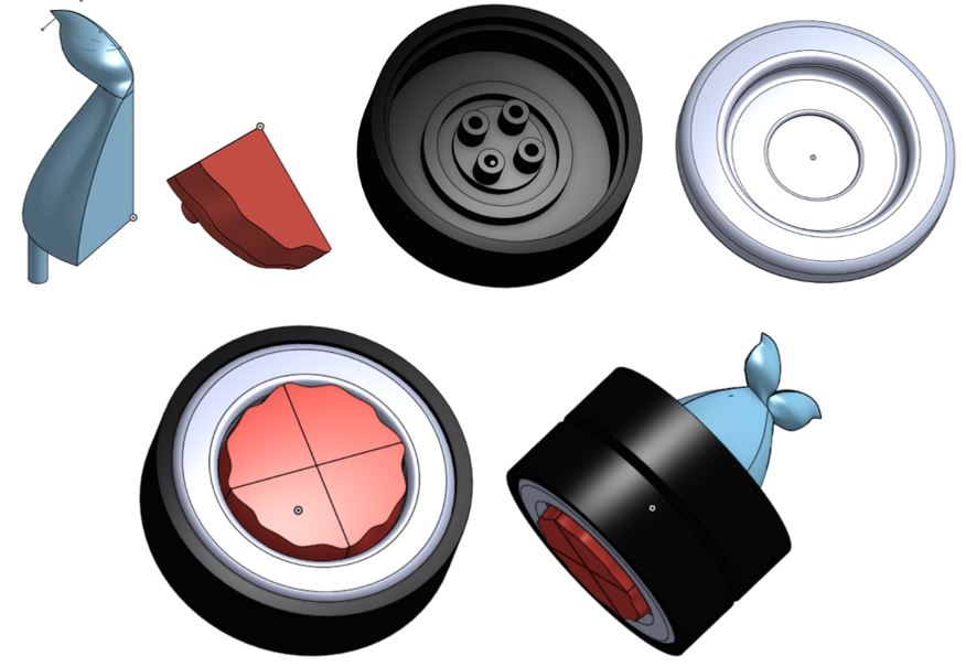 Fig 3: Parts / Assembly
 Fig 4: Exploded Assembly


(left to right) Fig 5 & 6 & 7: Production of base, fish fillings, and thermoformed rice


Fig 8 & 9: Fishtail components and them put together
When prototyping with additive manufacturing we made the rice, base, and sushi fillings using FDM and the fish tail using SLA to verify the correct relative dimensions in terms of function and aesthetics and to verify the minute dimensions connecting every part to one another. In addition, we also wanted to have a physical prototype of our yoyo to get a sense of how big each of our parts were when assembled in real life. However, when we received our parts, we realized we needed to adjust our tolerances according to the machine specifications since we were only able to force fit the one of the rice parts into one of the base parts, as shown in the picture below. Most of our parts failed to fit together due to the lower tolerances of the 3D printers.

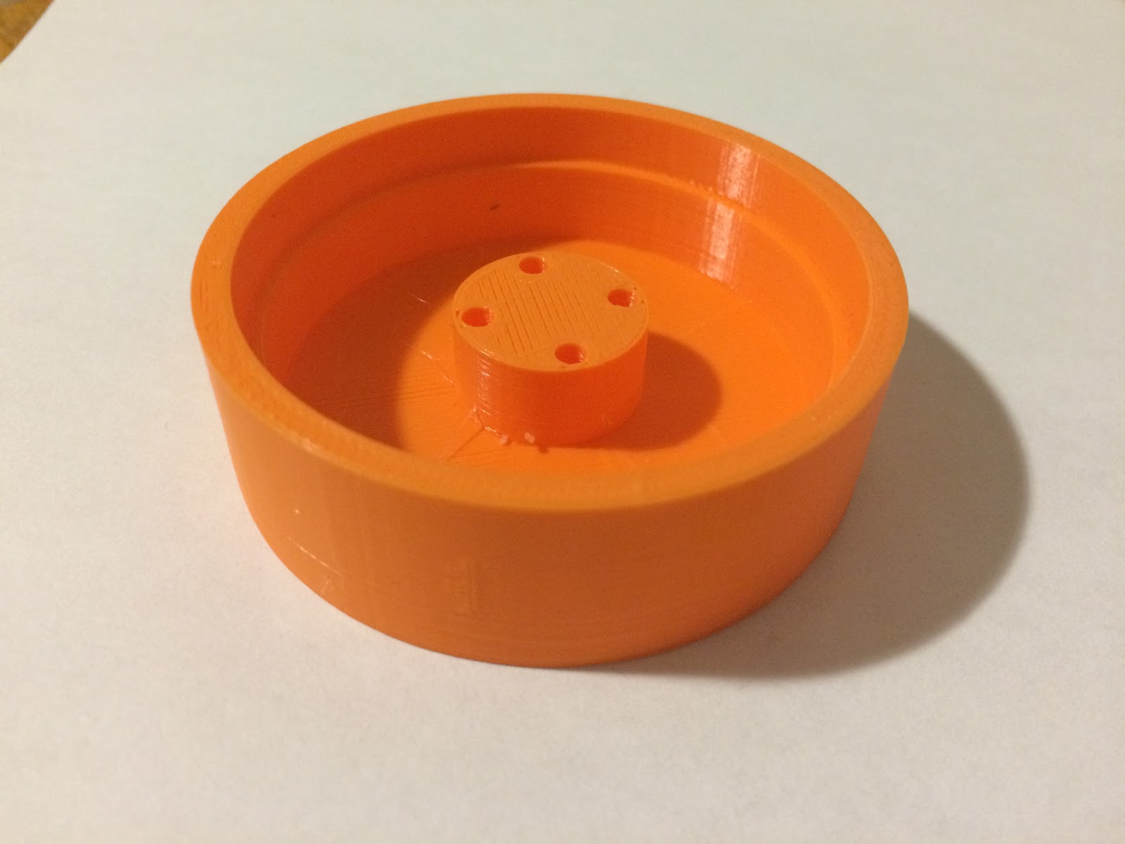
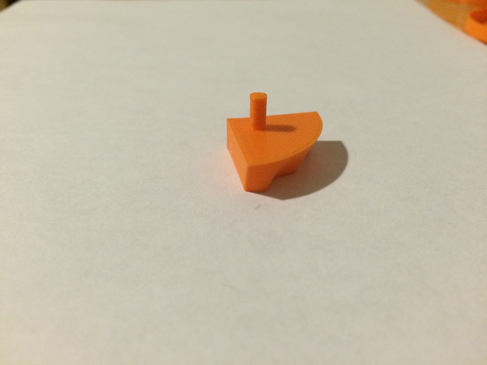
Fig 10, 11 & 12: (right to left) FDM printed rice, base, and fish filling.
Both the FDM and SLA 3D printers were able to print the general shape of our parts, and some details, such as the wavy surface of the sushi fillings and the curved fins of the fish tail, were achieved. However, in a comparison to the completed injection molded parts, there are several key differences. The main key difference between the two is time and money. Printing many parts, as performed in our cost analysis, is much more expensive than injection molding many parts. Secondly, it can over a day to fabricate one 3D printed part whereas an injection molded yoyo could theoretically be performed, if all production happening in series, in under 5 minutes. The level of detail is also a concern. With FDM, all small detailing is virtually lost since its tolerance isn't very small. Tolerancing also varies by production process. Injection molded parts do have a tendency to shrink during production while FDM printed parts may be larger than the specified dimensions. SLA, however, has extremely high accuracy that is on par with a well designed injection molded part. For our parts in particular, since a high accuracy is required for the press fit assembly, 3D printing in FDM would be highly undesired. Even for the rice thermoformed part, which has a high level of detail on its surface, FDM would not be an appropriate tool for fabrication. SLA would be better however, if we were to produce these on a mass scale, 3D printing would be extremely inefficient. Although 3D printing allows you to design more complicated shapes easier, we were able to achieve complex shapes through injection molding, (ie fishtail mold) and thus would provide no extra benefit on that front.
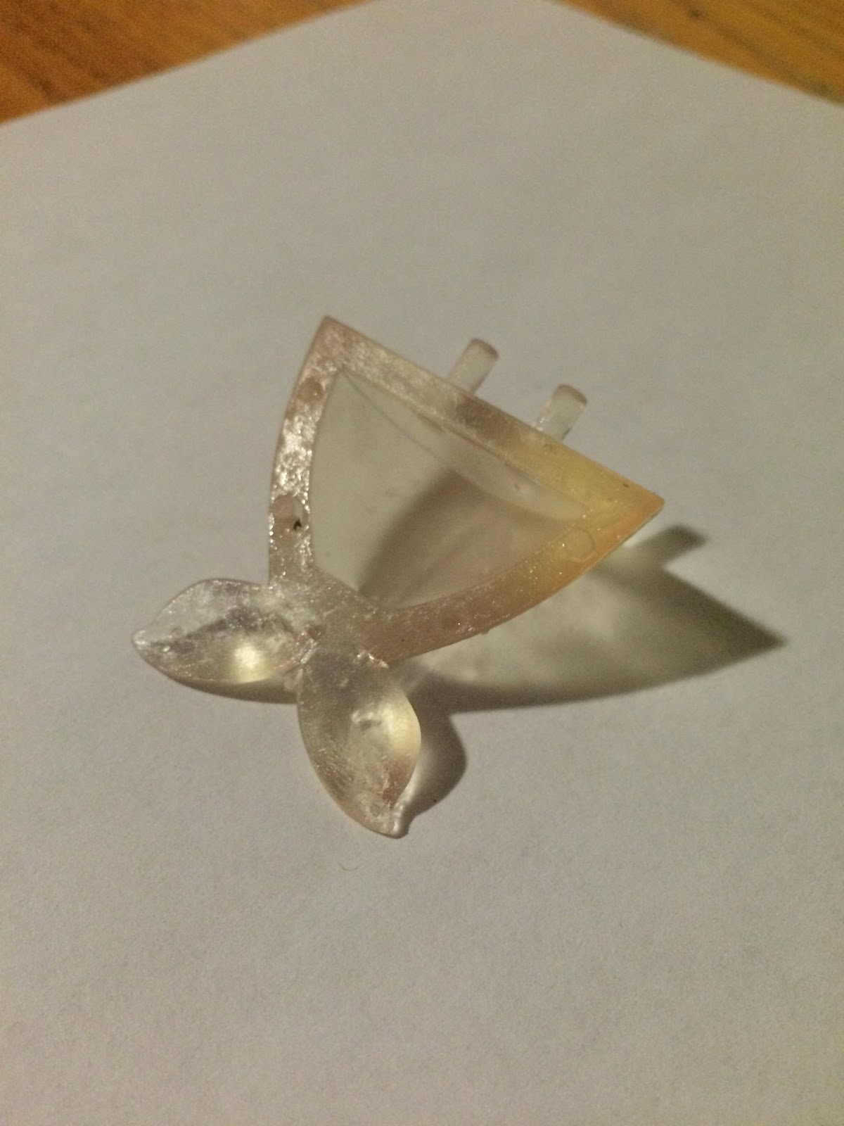
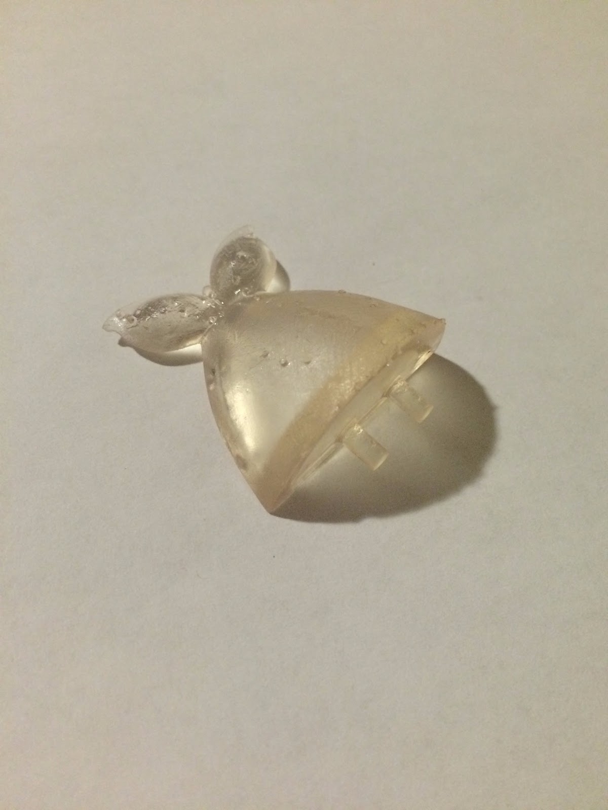

Fig 13, 14 & 15: (right to left) SLA printed fishtail at various angles
Table Comparison of the YY Design Specifications to the Measured Specifications
Original Design Specifications:
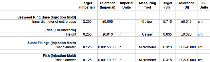
Measured Specifications:

As seen from the two tables above, three out of four of the critical dimensions decreased during the manufacturing process. The inner diameter of the base decreased the most from 2.250” to 2.222” and the post diameter of the fish tail shrank from 0.125” to 0.124”. Because the base and the fish tail are both injection molded, the differences in dimensions of the two parts were most likely due to uneven cooling times within each part. Additionally, the height of the rice decreased from 0.250” to 0.243”, most likely due to the relatively inaccurate stretching of the plastic sheet during the thermoforming process. We chose to do the height of the rice as the critical dimension instead of the outer diameter because the outer diameter was determined by the punch press and not the thermoforming process.
Although the sushi fillings met the target specifications of 0.125” post diameter, we think it would be better to change the post diameter to 0.124”, same as the post diameter of the fish tail. The sushi filling was a much tighter fit into the base than the fish tail, making it difficult to assemble. Compared to the base, the sushi fillings are much easier to adjust because the part is much smaller and thus experiences less of a shrinkage. Although the post diameter is determined by the diameter of the ejector pins and the premade ejector pins in the lab were 0.125” in diameter, it would be more beneficial for us to make 0.124” diameter ejector pins by ourselves for mass production. We’ll be able to use the same ejector pins for the sushi fillings and the fish tail, so tooling cost will not go up significantly.
If we were to use our current molds, our final table of specifications that we will apply to the mass production of our yo-yo is:

However, if we were to rebuild our molds, our final table of specifications will be:

We can achieve the above specifications by making the following changes:
- Making mold for the inner diameter of the base larger since the base didn’t shrink as much as expected
- Making the 3D printed mold for the rice a little taller
- Making ejector pins with 0.124” diameter for the sushi fillings and the fish tail
Summary of your Cost Analysis for Prototyping Versus Mass-Production
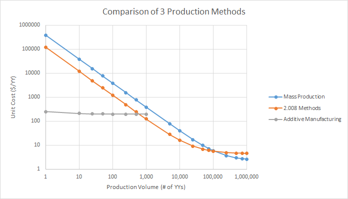
As we can see in the graph, different production methods are the most economically feasible for different production volumes. For low volumes, both the mass production methods and the 2.008 methods are several orders of magnitude more expensive than the additive manufacturing method. This is because additive manufacturing does not require the development of any infrastructure -- you’re outsourcing your parts to be made, so the other company takes the upfront cost of machinery and tooling, and they are able to use their business model of having a lot of different parts to print to lower the cost and spread the machinery cost across many different parts. For mass production and the 2.008 methods, the costs of the machines and tooling are very large and until there is a large enough production volume across which this price can be spread, the additive manufacturing prototype will be far more cost effective. This lasts until a production volume of around 700 YYs, when the 2.008 methods become more cost effective because the additive manufacturing is an almost constant price, but the 2.008 methods cost decreases with production volume, as the tooling cost and machine cost is spread out across more YYs.
The primary reason the mass production is more expensive than the 2.008 methods initially is that their molds and tools are more expensive. In order to be able to make more yoyos, the tools are of a higher quality and also have more cavities per mold and thus cost on the order of $100,000 for one mold. The IM and thermoforming machines used for mass production are also more expensive than the ones we use in LMP. After reaching a certain volume (from our graph it appears to be about 100,000 YYs), mass production becomes more cost effective than using 2.008 Methods and Materials. This is because the overhead cost for mass manufacturing is

The larger number of yoyos produced which explains why Case 3 tooling is so much cheaper than the 2.008 methods. The machine cost is the cost of the IM and Thermoforming machines which can be used to create these number of parts over its useful lifetime which is estimated to be around 10 years for both case 1 and 3.
The larger number of yoyos produced which explains why Case 3 tooling is so much cheaper than the 2.008 methods. The machine cost is the cost of the IM and Thermoforming machines which can be used to create these number of parts over its useful lifetime which is estimated to be around 10 years for both case 1 and 3.
The machine cost is one of the major cost differences between case 1 and case 3 (case 2 would not have a machine cost because you would only be paying for the final parts and not the machines themselves). There is such a staunch difference between case 1 and case 3 because at a much higher production volume, one can use different machines that are more suitable for the larger production volumes. For example, the Boy injection molding machine that we have at the LMP can only produce one part at a time, whereas larger-scale injection molding machines (some of which were seen in the lecture videos) have multiple sprues allowing them to create multiple parts at once. Based on the maximum mold size of some of the larger scaled injection molding machines that we found, we found that using a multi-part mold, you can injection mold up to 81 parts at once. This capability of producing multiple parts in one cycle allows us to operate at the large production volume (100,000 yoyos) without having to purchase multiple injection molding machines. This larger injection molding machine generally costs significantly more than the Boy machine in the LMP, but that higher cost is greatly mitigated by the amount of yoyos that are produced with it at large production volumes, decreasing the unit machining cost. The same idea applies to the thermoforming machine; while the larger thermoforming machines cost more than the one used in the LMP, because of how many parts are being produced with the machine, the cost of the machine is spread out over a much larger amount of parts.
The significance of these findings is that at low quantities of yoyos it makes no sense to create the molds ourselves and create these low volumes of parts instead of having them made with additive manufacturing. But, for this class, the cost of the mills, lathes, and HAAS (factored into the tooling cost in cases 1 and 3) are not factored into only our yoyos. Really the price of the mills and the injection molding machine are factored into each of the groups that create yoyos during the semester (over several years) as well as any other uses for the rest of the year, though we do not account for this in our model. If we did not have access to this equipment, it can be seen in section C that the point where machinery becomes beneficial, as compared to buying yoyos that were made with Additive Manufacturing is around 700 yoyos.
A significant cost factor in case 3 is the material cost because the cost of materials is just linearly proportional to the amount of yoyos that is being produced (for example if we doubled our production volume, the material cost would just double as well). Other costs are fixed or at least somewhat fixed, such that as you increase the production volume the fixed cost gets spread over a larger amount of yoyos, decreasing the unit cost. This is why the material cost of case 1 is the same as the material cost of case 3. Realistically, however, the cost of materials per unit weight would probably decrease as you increased the amount of the material that you were buying in a single order, but we did not include this in our cost model.
Reflection on the YOYOMATO Sushi YY Design
Overall, we were a little constrained by time, so we tried to design to avoid 3D machining as much as possible--for the sushi pieces and fish tail, we made rough cuts on the regular mill before switching to the Haas for the surfaces that absolutely had to be 3D machined. We made sure our dimensions were millable with standard tool parts and that they worked with existing 2.008 ejector pins (for example, making holes 0.126” so they would be the same size as ejector pins, and making corner radii about the same size as a tool). For the fish in particular, our biggest constraint was creating a mold that had perpendicular posts, since we couldn’t mill at 90 degrees. We ended up making two parting planes and splitting one of the posts along one of the parting planes. We also had to consider the 2.008 draft end mill tool very carefully when designing our second parting plane--it was a small plateau with a draft so the plateau would slip smoothly into the corresponding pocket, but we had to calculate the radius we needed to add to the corners based on the radius of the draft tool at that height. We also had to work with the 1/16” ball end mill since that was the smallest tool available for 3D machining--we ended up modifying our tool path to artistically incorporate the visible tool paths on the mold.
Similarly, with the sushi fish pieces, the texturing on top was the same size as existing 2.008 tools. We also needed a fillet at the bottom edge in order to fit into the base, but we had to increase the shell thickness because the ball end mill radius was too large to fillet a thinner shell. The thermoform mold for the rice ring was 3D printed, so we had to consider the height of the rice protrusions--too much and the plastic would not form completely to the mold; too little and the rice grains wouldn’t show up. The radius of each grain was determined by the material thickness (too small a radius for too thick a material, and the rice grains would not be clearly defined). Finally, for the yoyo base, we had to move the parting plane up to the middle of the yoyo in order to machine in the circular groove along the bottom of the base (to get even wall thickness). We wanted a ridge in the cavity mold but the tool was not long enough to cut out a ridge of the height we needed, so we moved down the parting plane and made the base thinner by about 0.40”.

To mass manufacture our yoyo, most of these considerations would carry over, and we would only make a few changes. First, we would have multi-cavity molds to increase production rates and take advantage of larger commercial injection-molding machines. For the base in particular, we would automate the shim/nut insertion and overmold around those pieces. For the rice pieces, we would have a larger mold that could create several rice pieces at once, and automate the process of punching out the ring’s center and outline. The rice ring mold would have to be made out of metal so it would last longer, but the fine, sharp corners where grains of rice intersect would end up filleted, even with a tiny tool. We might want to use laser sintering to 3D print a metal mold, in which case we wouldn’t have to change the design. When mass-manufacturing, the quality of the fish tail would need to be improved by making thinner posts (now that we would not be limited by 2.008 ejector pin size) so the fit into the base piece would be more consistent and yield rate would increase.


